|


 |  |
|
| |
 | Aeronautica | Comunicatii | Constructii | Electronica | Navigatie | Pompieri |
| Tehnica mecanica |
MECHANICAL DESIGN DESCRIPTION
CONTENTS
MECHANICAL DESIGN DESCRIPTION
1.- INTRODUCTION
2.- SCOPE OF DOCUMENT
3-DESCRIPTION OF THE DESIGNED INSTALLATIONS
3.1.- Pipes and fittings
3.1.1.- Pipes Stainless Steel
3.1.2.- Bends
3.1.3.- Flanges
3.1.4.- Reductions
3.2.- Welding
3.3.- Supports
3.4.- Seals
3.5.- Handrails
3.6.- Tramex
3.7.- Stairs
3.8.- Wall Passing
ANNEX I - LIST OF MECHANICAL DESIGN
ANNEX II - DRAWINGS OF MECHANICAL DESIGN
ANNEX III - WELDING PROCESS.
1.- INTRODUCTION
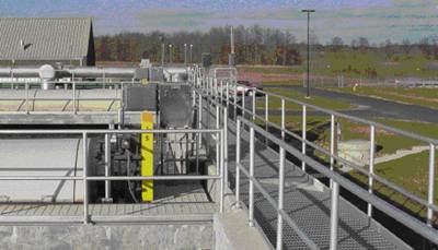
The purpose of this document is to describe the installations at the
waste water treatment plant in the
2.- SCOPE OF PROJECT
The scope of this document is describing all the mechanical design is going to be installed in the WWTP.
It includes all the stairs and handrails, supports of equipments and pipes, the pipes and all the fittings necessary in order to a correct installations and work.
3.- DESCRIPTION OF THE DESIGNED INSTALLATIONS
The main details of the mechanical design of the buildings are described below.
Pipes and fittings.
It will be used pipes of galvanized steel, stainless steel and HDPE. In drawings attached is represented the situations of the pipes with all the supports, flanges, bends. and all the fittings necessary in order to a correct installation.
All the pipes and fittings (bends, tees and reductions) will have an inscription with the followings data: Nominal Pressure (NP), Nominal Diameter (ND) and Material.
Drawing of details of pipes and fittings are enclosed in this Document (Annex II Drawings of Mechanical Design)
3.1.1.- Pipes Stainless Steel
All the pipes will be made of AISI 304, being the minimum values of the thickness the followings:
Individual sectioning of pipe work will be cut to the correct length and joined with loose flanges. The flange connections will have welded collars according to DIN 2642 PN 10 with loose flanges, which will be according to DIN 2642 or equivalent harmonized European Standards).
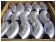
3.1.2.- Bends
All the bends will be made of AISI 304, being the minimum values of the thickness the followings:
All the bends will have a radio equal to 1,5 times the internal diameter of the pipe, for pipes ND ≤ 150. The rest of the bends will have a radio equal to the ND plus 100 mm.
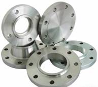
3.1.3.- Flanges
Flanges will be made of steel meeting the steel specification of the pipe material (AISI 304). They will be weld-on type and drilled to the application, NP 10 or NP16.
The flange connections will have welded collars according to DIN 2642 PN 10 with loose flanges, which will be according to DIN 2642 or equivalent harmonized European Standards).
Bolt, nuts and washers used in jointing at flanged valves will be of stainless steel type BS 320 S 21 or BS 304 S 15 to DIN 17007 or equivalent European Standards. The dimensions of bolts, nuts and washers will be in accordance with the flange dimensions.
3.1.4.- Reductions
All the reductions will be made of AISI 304, being the minimum values of the thickness the followings:
All the reductions will be concentric; the axis of the pipes of different diameter will coincide.
3.2.- Welding
For welding of stainless steel pipes and fittings in general, only will be applied TIG method with contribution stick of AISI 304. In the area of the welding zone will not be negatively altered and the intercristalline corrosion will not develop.
Only certified welding and certified welders will be used.
Drawing of details of welding are enclosed in this Document (Annex II Drawings of Mechanical Design)
Supports.
All necessary supports will be installed in order to support the pipes and the equipments. They will be made of stainless steel.
Supports of pipes will be installed:
Maximum each 2 m Lengths of pipe longer than 5 m and ND ≤ 200mm.
(if it is not specified in drawings)
Maximum each 1,50 m Lengths of pipe longer than 5 m and ND > 200mm.
(if it is not specified in drawings)
In every change of direction.
In every exit or enter to equipments with a maximum distance of 1 m.
The welding of supports in general will be made with electrodes.
Drawing of details of supports are enclosed in this Document (Annex II Drawings of Mechanical Design)
Seals.
Seals of neoprene will be installed in all the joints flange-flange or flange-equipment.
Handrails.
The handrails will be made of galvanised steel according to DIN 24533 with handrails and standards to withstand a horizontal force at handrail level of 740 N/m run.
Standards and handrails will have
Horizontal mounting flanges will be drilled for three bolts with two bolts on a line parallel to and one on the walkway side of the line of the handrail. Vertical mounting flanges will be drilled for two bolts on the line through the bolts being vertical.
Bolts, nuts and washers will be made of stainless steel.
Drawing of details of handrails are enclosed in this Document (Annex II Drawings of Mechanical Design)
Tramex.
Tramex will be made of galvanized steel. It will be composed of three parts: portent frame, separating frame (bars) and perimeter plate. It will be used tramex of 30x30x2 mm and it will be prepared to support a load of 500kg/m2.
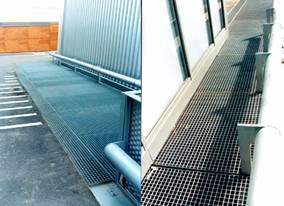
Drawing of details of tramex are enclosed in this Document (Annex II Drawings of Mechanical Design)
Stairs.
The stairs will be made of galvanized steel. It will be composed of metallic structure UPN80 and the steps will be made in tramex of 30x30x2 mm and a portent load of 500kg/m2.
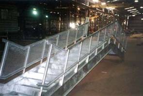
All the stairs will have handrails described in point 3.1 of this document. They will be made of galvanised steel according to DIN 24533 with handrails and standards to withstand a horizontal force at handrail level of 740 N/m run.
Drawing of details of stairs are enclosed in this Document (Annex II Drawings of Mechanical Design)
Wall passing.
When pipes pass through a concrete wall or structure, they will project
from the external face of the structure by 300mm for pipes with nominal bores
of 500 mm or less. For pipes with nominal bores in excess of 500 mm, the pipe
will project from the external face of the structure by
Drawing of details of wall passing are enclosed in this Document (Annex II Drawings of Mechanical Design)
ANNEX I: MECHANICAL DESIGN LIST
ANNX II: MECHANICAL DESIGN DRAWINGS
ANNEX III: WELDING PROCESS
Copyright © 2025 - Toate drepturile rezervate