|


 |  |
|
| |
 | Aeronautica | Comunicatii | Constructii | Electronica | Navigatie | Pompieri |
| Tehnica mecanica |
Faculty of
Industrial Robot Section
DESIGNING A THREE FINGER GRIPPER
HAVING A SWING-BAR
MECHANISM ,ACTUATED PNEUMATICALLY
CONTENT
CHAPTER TITLE
INTRODUCTION
THE CONSTRUCTIVE VARIANTS
THE QUALITY CHARACTERISTICS AND THEIR HIERARCHY
THE BEST VARIANT SELECTED WITH PUG
THE DETAILED DRAWING OF THE PREHENSOR
PLANNING THE QULITY OF THE PRODUCT
THE CALCULATION OF THE GRASPING FORCE
THE COST OBJECTIVE
CHOOSING THE SENSOR
THE DRAWING OF THE ENSEMBLE 2D
11. BIBLIOGRPHY
Chapter 1
INTRODUCTION
THE TECHNICAL DATA
Dmin=35 mm ;
Dmax=70 mm ;
kg/m^
a max=1 m/s^2 .
Dmin ; Dmax [mm] -minimum and maximum diameter of the cylindrical parts ;
[kg/m^3] -material density ;
a max [m/s^2] -maximum acceleration in vertical motion .
THE REQUIREMENTS
It is required to design a three fingers prehension mechanism from an industrial robot structure in order to handle cylindrical parts.The mechanism is pneumatic actuated.It is imposed to incorporate a force sensor in the fingers.
THE MECHANISM
The studied mechanism is THE SWING-BAR MECHANISM .
It is very important that the transmission systems used in the case of industrial robots to maximize the strength of the system in parallel with the minimization of weight , inertia and elasticity.Transmission systems represent the main source of vibrations , dry and viscous friction ,which lead to significant energy losses within the robot mechanical system.
Further, I am going to compare the swing-bar mechanism with the gear mechanism , for example.An important aspect , when analizing the mechanisms , is the friction , as I have mentioned above ,too.From this point of view the swing-bar mechanism has less friction between its elements than the gear one (the gears in motion have a high friction between their teeth and from this comes a high wear in time ,too).Some of the main advantages of the swing-bar mechanism are : it has a good accuracy (at the geared one this depends on the teeth) ;it has a low gauge and a small weight (the elements are lighter than the gears) ; it is still , it isn't noisy (the gears in motion are producing a lot of noises) ; it has a simple structure (it has no complicated shapes or elements).
Everything has advantages and disadvantages and as I spoke above about the advantages I will do the same thing for the disadvantages , too.The main disadvantages of the swing-bar mechanism are : it isn't so compact as the geared one;it can't lift big weights.
Chapter 2
THE CONSTRUCTIVE VARIANTS
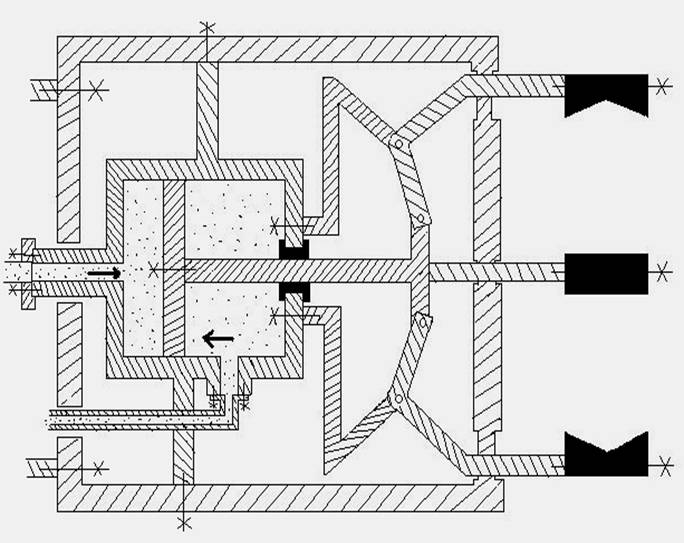
First variant
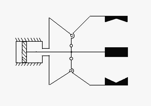
This variant of the swing-bar mechanism has the following component elements:
a pneumatic cylinder with a piston for the translation motion ;
a bar wich makes the connection between the piston of the pneumatic cylinder and the three fingers wich are actuated with the help of:
three mobile joints
three fixed joints
the fingers with special ends for grasping the cylindrical parts.
The functioning principle:
when the piston of the pneumatic cylinder goes to the right,the three mobile joint that are fixed on the piston goes to,and transmit the motion to the other three joints that makes the fingers to open ,so the gripper will release the part , when the piston goes to left the joint make the fingers to close and grasp the part.
2.2 Second variant
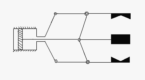
This variant of the swing-bar mechanism has the following component elements:
a pneumatic cylinder with a piston for the translation motion ;
a bar wich makes the connection between the piston of the pneumatic cylinder and the three fingers wich are actuated with the help of:
six mobile joints
three fixed joints
the fingers with special ends for grasping the cylindrical parts.
The functioning principle:
the functioning principle is based on ,the moves that the piston is making ,the to basics
moves to the left and to the right.the gripper has on the piston three mobile joint to
treansmit the move,another three mobile joints on the three fingers at their middle and the
three fixed joints at the beginning ,when the piston goes to right the fingers wiil open and
when the piston goes to left the fingers will close.
2.3 Third variant
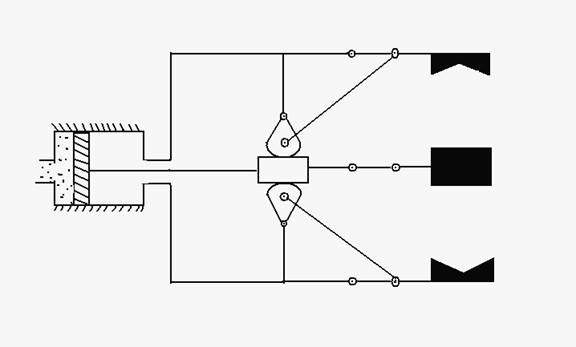
As it can be seen in the drawing(the variant) above this mechanism is formed of:
a pneumatic cylinder with piston , which makes a translation motion;
a swinging-bar which motion is simultaneously with the motion of the piston , this bar is in reality with teeth ;
three cons with mobile joints ;
three fingers at 120 degrees distance one from another , with a special form at their ends for manipulating cylindrical parts ;
The functioning for this first variant :
when the piston of the pneumatic cylinder is translated to the right , the geared bar goes to the right , too making the cones going in the opposite way ,to the left through the joints and the bars , so the fingers will be opened.When the piston of the pneumatic cylinder is going to the left all the elements mentioned above are going in the opposite way and the fingers will closed.
CHAPTER 3.
THE QUALITY CHARACTERISTICS AND THEIR HIERARCHY
To obtain quality is necessary a lot of work and a lot of skill to accomplish some requirements,you need to follow certain criteria.These criteria , after settled , they need to be ranked in order of their importance-for example with AHP method.The quality requiremqnts for the swing-bar mechanism are :
REDUCED NOISE
LOW COST
EASY TO ASSEMBLE
EASY TO ATTACH ON THE ROBOT FLENGE
HIGH ACCURACY
DESIGNED FOR RECYCLING
EASY TO MAINTAIN
LOW ACTING FORCES
SMALL WEIGHT
SMALL GAUGE
HIGH RELIABILITY
HIGH DEGREE OF UNIVERSALITY
These are the requirements that were set by the customer ,reqirements that the designer has to take in account during the design process.
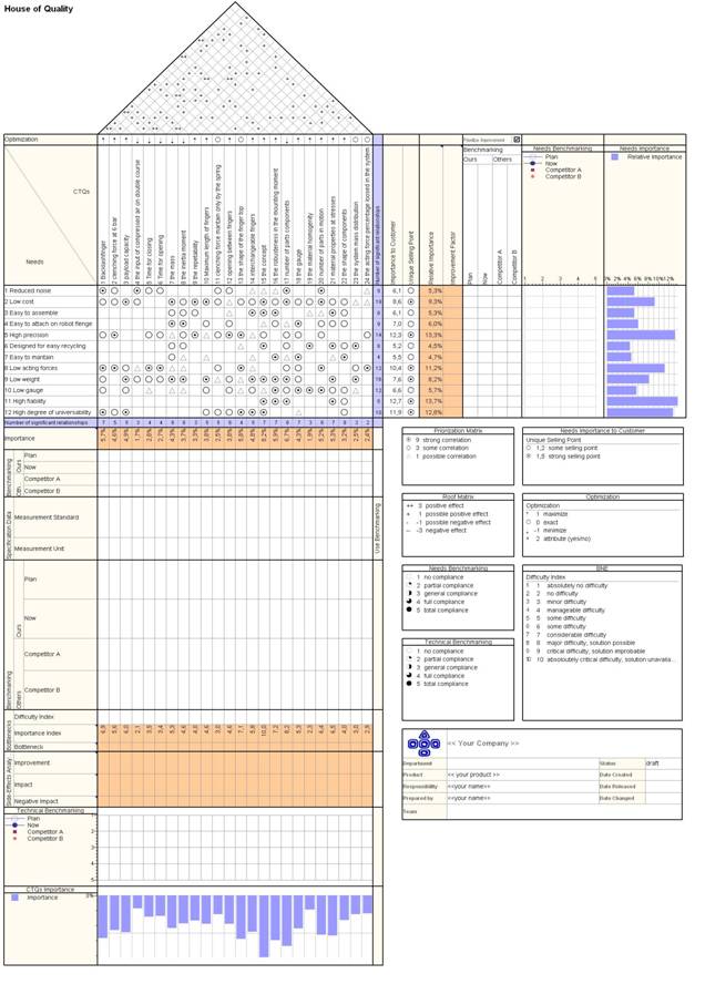
The following step in the process of designing will be ,the introducing of these requirements into an program named Qualica qfd ,to be more precise the AHP method .
This method is used to assure a n easy ierarhizations of these requirements ,having as a result ,a ierarhization takent into account the importance of each characteristic in the process of designing ,to obtain an competitive module an competitive gripper .
So, in the next page will be presented the AHP that was made for this ierarhization,and the explinings appropriate to him.
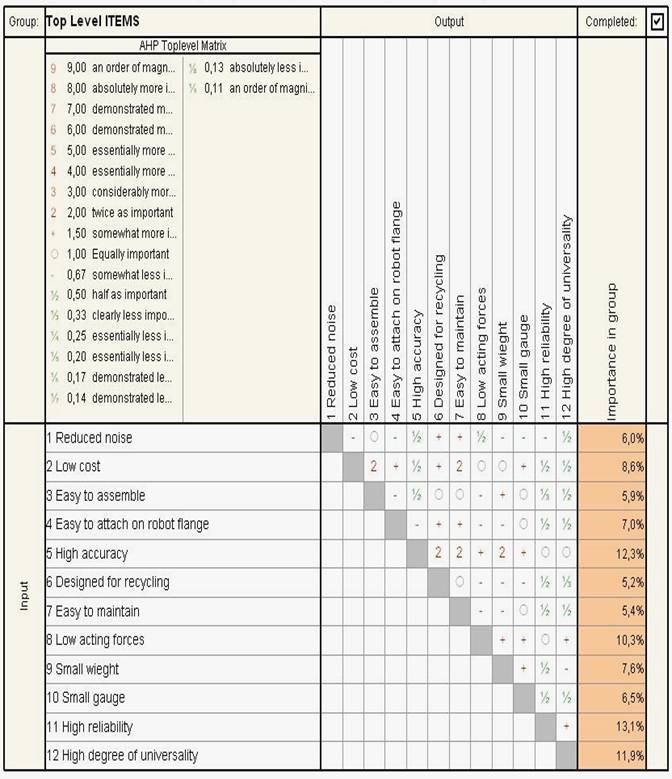
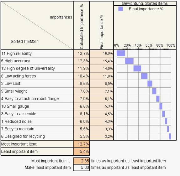
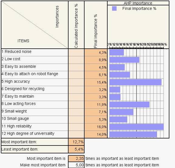
After completing the AHP method the results are :
most important characteristic is the reliability followed closer by accuracy ,and the most less important characteristic is design for recycling, but also must be mentioned that all characteristic are important ,but this ierarhization shows wich characteristic has a bigger percentage in the designing process for obtaing an competitive result.
CHAPTER 4.
THE BEST VARIANT SELECTED WITH PUGH
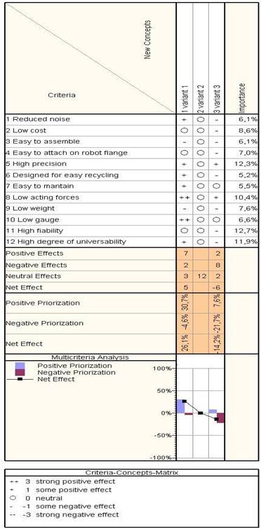
the result is that the best variant is variant number 1 (presented bellow)
This is the final variant that was choosen with pugh method:
this variant will be further analized ,presented as a detailed draw and a 2D final drawing.
the method pugh from the Qualica package help us to make a ierarhization of the good and wick points of each variant offering us at the end the better solution ,solution that without this program had been difficult to analize and choose the better one, that is recommende to use special programs that help us to find the bettewr way,the optim way , for a good designing of the prehension mechanism .
CHAPTER 5
THE DETAILED DRAWING OF THE PREHENSOR
CHAPTER 6.
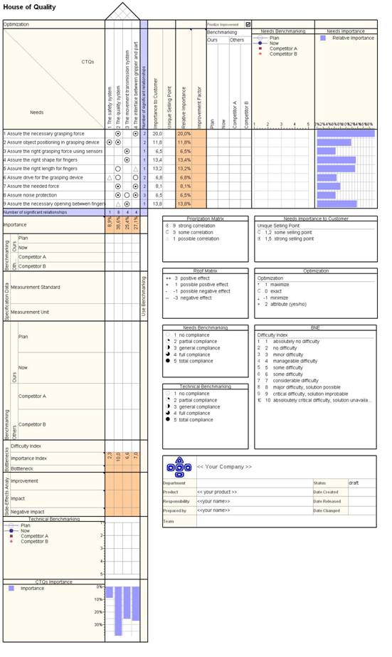
PLANNING THE QUALITY OF THE PRODUCT WITH QFD METHOD
THE MOST IMPORTANT QULITY CHARACTERISTICS
THE CONCEPT
THE GAUGE
THE NUMBER OF COMPONENTS
THE MASS
THE PAYLOAD CAPACITY
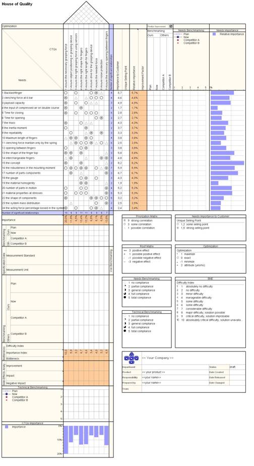
Next we will plan the quality characteristics with the qfd method ,a qfd with customer requirements as needs,and the quality characteristics as CTOs (quality characteristics).
(next page)
Mind-map method
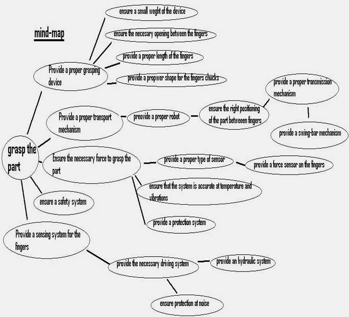
This method was applied to help us to complete the first QFD from the page 15, QFD that will also be helped in making it by another method the FAST method that will be presented in the next page (page 17).
THE FAST METHOD
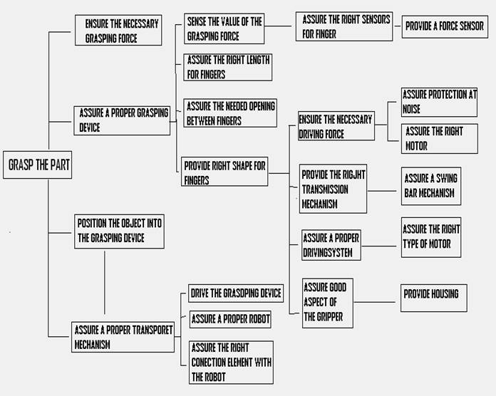
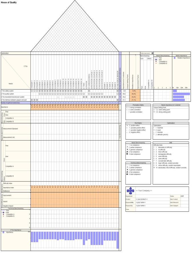
the next few pages will present three qfd's, that will help us in the process of optimization a nd in the process of designing ,offering us possibility to see if thre are some conflicts some interferences between different functions,or characteristics or different relations that might help us during the process of improving ,first qfd is between engenering caracteristics (as needs) and the functions of the gripper (-theCTOs-),second qfd between the functions of the gripper(as needs) and the modules of the gripper(as CTOs), and the third qfd is between the modules of the gripper(as needs) and the parts of the hole assembly(as CTOs),these wiil be presented further.
CHAPTER 7.
THE CALCULATION OF THE GRASPING FORCE
The data's are:
Dmin = 35 [mm]
Dmin = mm]
![]()
![]() =1
=1
![]()
K=1.5-2
![]()
sin![]()
g = 9.8 m/s![]()
![]() -transmission force [N]
-transmission force [N]
![]() -grasping force [N]
-grasping force [N]
k-safety coefficient
m-the mass [kg]
G- heavy force [N]
g- gravitational force [N]
d-diameter [mm]
![]() friction force [N]
friction force [N]
![]() - friction coefficient
- friction coefficient
N-normal force
Because the calculation of the grasping force includes two diameters ( Dmin, Dmax) the calcutions will be made for each diameter once for Dmin , and once for the Dmax :
1.Calculations for Dmin = 35 [mm]
a)
0.8![]()
![]()
![]()
![]()
![]()
![]()
b) Having the length we find the volum in proper to find the mass ,that is our purpose, the mass of the body that the grasping force is acting ,and at the end to find the grasping force.
L=25 [mm]
![]()
![]()
![]()
m = 2.4![]() 3 10
3 10![]() = 0.07 [kg]
= 0.07 [kg]
c) Now finally we will calculate the grasping force, because we have all the data we need:
m=0.07[kg]
Fg-grasping force
![]()
![]()
![]()
![]() N=
N=![]()
![]()
![]()
![]()
![]() 0.116 [N]
0.116 [N]
2) The calculations for the second diameter:
a)
0.8![]()
![]()
![]()
![]()
![]()
![]()
b)
L=105 [mm]
![]()
![]()
![]()
m = 4.03![]() 3 10
3 10![]() = 1.209[kg]
= 1.209[kg]
c)
m=1.209 [kg]
Fg-grasping force
![]()
![]()
![]()
![]() N=
N=![]()
![]()
![]()
![]()
![]() 2.01 [N]
2.01 [N]
CHAPTER 8
THE COST OBJECTIVE
At the begining of the project ,our project was set to be a project that wil design an gripper who's cost objective will be 1000 $,so all the components prices together must not reach 1000 $.The cost objective will be realize with the help of the qfd where were introduced each component,and for each component was obtained a percentage .
This percent give the importance of each component in the project and reporting to those 1000 $ we will obtain a value for each component.there will be two colons one with the calculated prices (method presented above ; taken from qfd),and the real prices of components,in this way obtaining two gripper costs : one calculated and one real .
Calculation price Real price(between)
- fingers- 32 $ 25-32 $
- screws-(4-10,12-13,18-20) (in QFD) 23 $ 3-5 $
- screws-(11,14-17) 27 $ 5-7 $
- tank - 41 $ 35-41 $
- piston- 27 $ 20-27 $
- case- 23 $ 19-22 $
- rotation couples 41 $ 30-41 $
- bar- 27 $ 20-27 $
- sensor- 53 $ 13.75 $
Total cost 1023 $ 635 $
CHAPTER 9
CHOOSING THE SENSOR
Because we need to measure the grasping force we need a force sensor; I have chosen the sensor Flexi force A 201, and placed on the finger tip between the finger and part.The sensor and it's characteristics will be presented below:
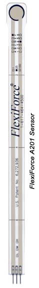 Fig.14.1 FlexiForce A201 Sensor
It is an ultra-thin sensor , flexible , customizabile and cost-effective (4 sensors=55$).
Further will be detailed some catalogue data for this sensor:
|
|
|||||||||||||||||||||||||||||||||||||||||||||||||||
See recommended drive circuit. In order to measure forces above 100 lbs. (up to 1000 lbs.), apply a lower drive voltage and reduce the resistance of the feedback resistor (1 kΩ min).
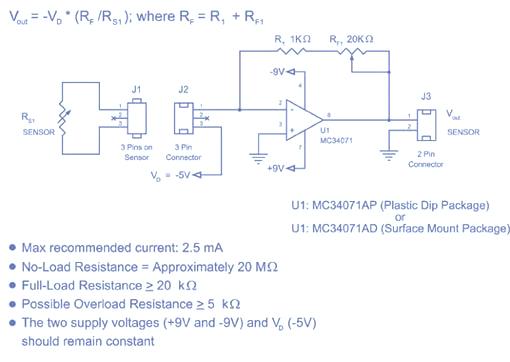
Example of excitation circuit
Fig.14.2 Data from the catalogue about the sensor
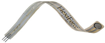 Fig.
14.3 The flexible force sensor
Fig.
14.3 The flexible force sensor
CHAPTER 10.
THE DRAWING OF THE ENSSEMBLE 2D
The drawing will be presented separately on a A1 sheet.
CHAPTER 11
BIBLIOGRAPHY
1.'FUNDAMENTALS OF COMPETITIVE DESIGN IN ROBOTICS' - STELIAN BRAD
2.'ACTIONARI PNEUMATICE ' - IOAN POP
3.WWW.GOOGLE.COM
4.WWW.TEKSCAN.COM
Copyright © 2025 - Toate drepturile rezervate