|


 |  |
|
| |
 | Biologie | Chimie | Didactica | Fizica | Geografie | Informatica |
| Istorie | Literatura | Matematica | Psihologie |
UNIVERSITATEA POLITEHNICA
FACULTATEA DE AUTOMATICA SI CALCULATOARE
TELECOMUNICATII PE FIBRE OPTICE
Referat
Cuprins:
1.Introducere
2.Fibrele optice in LAN
3.Operatiile si functiile de baza intr-un sistem tipic de transmisii
4.Tipurile de fibre optice, structura si principalele aplicatii
1.Introducere
Utilizarea (transportul ) luminii la distanta mare in telecomunicatii nu este un concept nou. In mitologia greaca Tezeu trimitea informatii tatalui sau Egeus prin selectarea culorilor navelor sale . In vremuri mai apropiate indienii americani comunicau folosind semnale de fum iar englezii foloseau focuri mari pentru semnalizarea trupelor spaniole din Armada. La sfarsitul secolului 18 Claude Chappe a realizat un system telegraphic ce utiliza lumina plasata in varful unor dealuri(sistemul a functionat in franta pana la aparatul telephonic electric). Mai recent se foloseau semnale luminoase codate pentru transmiterea semnalelor.
Marea realizare a timpurilor noastre consta in posibilitatea producerii unor raze luminoase modulate in inalta frecventra care pot fi transmise la mari distante folosind filter realizate din sticle de inalta puritate. Blocurile de intrare si de iesire permit codarea si eecodarea si modularea si demodularea.
Acum o suta de ani john Tyndall a demonstrat experimental ca lumina poate fi ghidata prin reflexii successive intr-un mediu transparent(apa) inconjurat de un alt mediu cu indicele de refractie mai mic(aer). In 1910 Peter J.W. Debye a sugerat idea transmiterii luminii la distanta folosind un material "gazda" de ghidare care este un material cu variatii ale indicelui de refractie. Ideea a fost completata dupa 1960 odata cu aparitia in conceptual comunicatiilor moderne. Au fost facuti mai multi pasi:
-inventarea diodei electroluminiscente (LED) cu durata mare de viata si prêt de cost mult mai mic decat al laserilor
-introducerea in 1970 a filtrefor cu atenuare de faza
Capacitatea unei fibre optice de a functiona ca ghid pentru lumina se bazeza pe legile fizice bine cunoscute ale reflexiei si refractiei la interfata dintre doua medii cu indici de refractie diferiti.Consideram ca daca o raza monocromatica de lumina propaganda-se intr-un mediu cu indicele de refractie mare intalneste un mediu cu indicele de refractie mic, reflexia totala apare cand unghiul de incidenta este mai mic decat valoarea critica.
Cele mai importante domenii de utilizare a fibrelor optice le reprezinta comunicatiile telefonica, transmisiile de date, transmisia programelor de televiziune. S-au montat cabluri optice intre continental American sic el European. Ca avantaje deosebite consideram imunitatea totala la interferente cu campuri megnetice exterioare, dimensiuni si masa redusa, imposibilitatea de spionare a semnalelor transmise.
Utilizari in domeniul civil:
-trasmisii de date
-controlul sistemelor in statii de putere(inclusive instalatii nucleare)
-retele locale de birouri sau fabrici
-instalatii feroviare
-conectarea unitatii centrale a unui computer cu terminalele
-sisteme de telecomunicatii nebruiate prin interferente exterioare
-instalatii interne in avioane, trenuri, nace
-ghiduri pentru rachete
-sisteme radar
Astfel datorita lipsei interferentei intre canale cae mai importanta aplicatie a fibrelor optice si cablurilor optice este domeniul comunicatiilor. Datorita alterarii semnalului pe transee lungi este necesara intrclasarea in diferite puncte a unuor echipamente electronice amplificataore. Coeficientii de atenuare ai fibrelor optice sunt mult mai mici dacat ai conductoarelor metalicw din cupru. Pentru transmiterea la 0.85 μm se folosesc echipamente intercalate la 10 . 15 km iar 1.3 μm la 20 . 30 km. Se folosesc sisteme PCM pentru trnsmisii de 2, 8, 34, sau 140 Mbit/s corespunzand la 30, 120, 480 sau 1920 de canale pe pereche de fibre. Pentru aplicatii laser de laborator utilizand fibre de mod uic este necesar un elemnt de regenerare a semnalului la 100 km.
In anumite situatii semnalul analogic este preferat celui digital (in cazul transmiterii semnalului de televiziune).
Se folosesc doua surse de lumina:
-LED-diode electroluminiscente
-LD-diode laser
Diodele LED au durata deviate(peste 100000 ore), prêt scazut, emit lumina intru-un domeniu spectral de tip banda. Diodele LD costa mult , au timp de viata redus, puterea luminoasa a semnalului monochromatic este mare(se preteaza la modulare).
2.Fibrele optice in LAN
Beneficile folosirii fibrelor optice; comparand cu traditionalele cabluri coaxiale ; comparand cu wireless communication si cu undele radio . De asemenea si care sunt problemele care apar la folosirea fibrelor optice in telecominicatii.
Principalele avantaje ale fiberei optice :
-atenuarea scazuta (in comparative cu oricare din tipurile de cabluri enumerate mai sus), distante lungi in comparative cu wireless communication.
-de dimensiuni mici
-mai luminoase
-intrefete mai putin sensibile(albe, zgomot rozaliu care provine de la surse de lumina puternice). Semnalul nu mai este electric, astfel nu exista riscuri electrice
-banda larga de transmitere
-posibilitate de acoperire mare
-este un mediu care ramane in top sip e viitor pentru ca se pot realiza noi aplicatii in domeniul comunicatiilor pe banda.
-datele sunt sigure.
Dezavantajele folosirii fibrelor optice:
-dificil de instalat, este nevoie de personae calificate pentru a realize legaturile
-nu sunt asa de elastice , usor de rupt
-este nevoie de tehnologie inalta
-cotactul cu laserul dauneaza foarte tare omului
-foarte scump pentru setare.
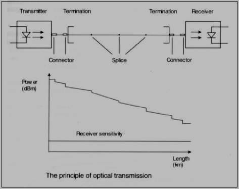
3.Operatiile si functiile de baza intr-un sistem tipic de transmisii
|
|
|
|
|
Fig 1: functiile transmiterii pe fibre optice.
Cand lumina a ajuns la capatul celalalt va trebui realizat un nou pas , si anume acele de conversie a bancului de date intr-un semnal electric. Se folosesc senzori de lumina (PIN sau diode avalansa) ca Receivere. Astfel fiacare device clasic poate interpreta semnalul . Conectarea inca trebuie sa fie foarte curate, in alte cazuri funtionarea corecta va fi afectata.
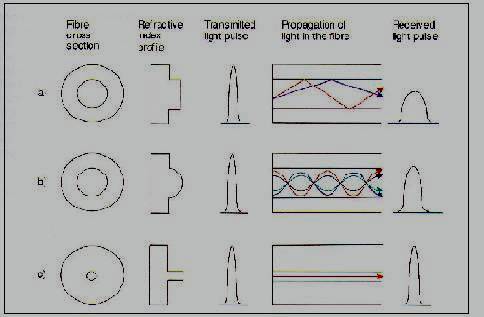
4.Tipurile de fibre optice, structura si principalele aplicatii
Tipurile de baza ale fibrelor opticepot fi impartite in doua categorii daca luam in considerare indexul lor de refractivitate si propagarea luminii in interiorul fibrei. Cele doua categorii sunt:
1.Multimode
2.Single-mode
Aceste doua grupuri au si subclase , astfel rezulta clasele principale:
Step index multimode fiber (nu se folosesc in zile noastre)
Graded index multimode fiber
Single-mode fiber.
|
|
Fig2: a) Step index multimode fiber,
b) Graded index multimode fiber
c) Single-mode fiber.
The most important fiber types are the following:
Multimode fibers:
50/125 μm
62.5/125 μm
100/140 μm
Numbers refer to the diameter of the core or the mode field and the cladding.
Single-mode fibers:
Single-mode fiber (dispersion-unshifted 9/125 μm), SM, (ITU-T G.652)
Dispersion shifted single-mode fiber (8/125 μm), DS, (ITU-T G.653)
Non-zero dispersion shifted single-mode fiber (ITU-T G.655)
Some of the basic fiber optic applications are in Telecommunications, Local Area Networks (LANs), Wide Area Networks (WANs), Factory Automation and in Premises Wiring.
The very first fiber optic application was created in the late 1970s and it was the Multimode PDH (Plesiochronous Digital Hierarchy) and then came the Single-mode PDH in the early 1980s. Then followed the Single-mode SDH (Synchronous Digital Hierarchy), the PON, the Optical amplifier, and the WDM (Wavelength p;
5.Atenuarea luminii in fibrele optice.Metodele de reducere a atenuarii in transmisiile prin fibre optice.
Attenuation of light in optical fiber can be described as a loss of power in the signal. It means that the wave shape decreases as long as it travels through the fiber. Because the signal in the optical fiber can only take two different values, which are "0" or "1", it is necessary to maintain its level in some defined ranges. Attenuation is the opposite phenomenon of amplification, and has to be taken very seriously in long distance connection or network. It seems obvious that the longer the optic fiber cable is the greater the attenuation will be. So to reduce this undesirable effect, we can place amplification devices to keep the signal understandable by the next stage.
Attenuation is expressed in dB/km
Absorption and scattering are two main factors creating attenuation. We will define those two effects:
Absorption is the loss or Infrared and UltraViolet due to unwanted material in the fiber.
Scattering is the loss of power in the signal because of the refractive property of the fiber. Some energy is lost in this phenomenon. This is due to non-uniformity in the fused silica.
Progress along the years:
Silica fused SiO2: 1970 20 dB/km
1975 2 dB/km
1985 0.5 dB/km
1995 0.2 dB/km
2002 0.17 dB/km
2003
This last value (0.17dB/km) is very close to the theoretical minimum.
6.Dispersia modala si materiala in fibra optica. Modul in care dispersia modifica informatia digitala a semnalului in fibra optica.
Dispersion is signal distortion caused by some modes that require more time to propagate than others. It distorts both analog and digital signals. In a digitally-modulated one, it causes the received pulse to be spread out in time.
Material dispersion - in single-mode fibers, the most significant dispersion is chromatic dispersion, which also consists of waveguide dispersion. Meaning that slightly different wavelengths of the optical signal have slightly different propagation velocities in the fibre. Chromatic dispersion is measured in picoseconds over nanoseconds in kilometer. As a material property of the fiber, it's numerical value does not change during the cable manufacturing.
Modal dispersion - occurs in multimode fibers as light travels a different path for each mode. The direct signal is distorted by a reflected signal arriving a short time later. In a long cable, the stretching and the summing of all of the fiber's modes cause a lengthening effect of launched optical pulse. Modal distortions limit the bandwidth of multimode fibers.
7. Specificatiile tehnice pentru structurile de fibre optice MM si SM
Single-mode fibers:
small diameter of core: 5 to 10 μm
potential bandwidth up to 100 GHz-km
1300 to 1500 nm wavelength systems
low attenuation
higher bandwidth than multi-mode fibers (less dispersion)
Multi-mode fibers:
higher attenuation than single-mode
lower bandwidth in a fibre, because of the modal and chromatic dispersion
larger mode field diameter (usually around 50 μm)
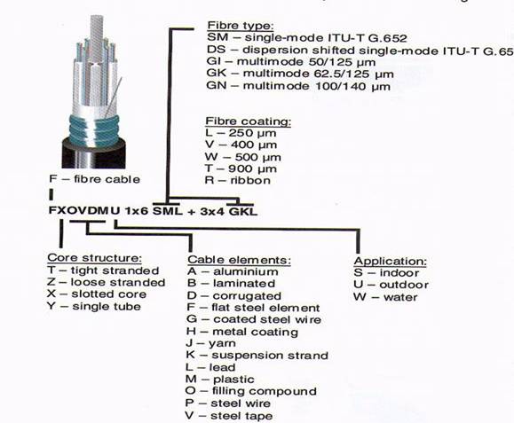
Cable specifications, needed during cable handling and installation:
cable type
fibre type
number of fibers
fibre coating
cores structure
8.Cum se transmite informatia in legaturile prin fibra optica. Modularea informatiei in semnale luminoase. Diferenta de modulare daca se face compatatia cu cablurile electrice si/sau undele radio.
The data's journey in the fibre starts with the device that will convert the electric signal into light signal pulses coded. In order to perform this delicate conversion we have to use a source of light having precise requirements. Naturally, we can't use basic lamp. Nowadays, different kinds of light emitting devices are available on the market. They are Light Emitting Diodes, and the Laser. In a few words (see next chapter for more details), the LEDs are more widely spread than the laser. Mostly because the LEDs are less expensive and easier to use compare to the lasers even if those provide better signals.
Once the electric signal has been converted into binary light pulses, the data will follow its way in the fibre. We can find different fibres, depending on the material used (fused silica or glass) and their requirements (the distance, the environment, the cost . ). We may suggest that in case of long distance, repeaters (or amplifications) must be installed. The attenuation would lower the signal and then not be understood by the receiver.
So, the receiver performs now the task of converting (and maybe decoding) the light signal into electrical signal. The sensor used can be photo diode or avalanche diode. The data is now back to its electrical shape.
Of course, when the data is light pulses in the fibre, the signal itself goes through different steps and modifications before the transmitters -beside the fact that it always remains digital-. In order to get a greater bandwidth, which means transmitting more data in the same amount of time, we modulate the signals. It means that we can combine, at once, different data coming from different units (data1, data2 . datan). One way to modulate is to assign for each data (data1, data2 . datan) one wavelength (w1, w2 . wn).
In the radio wave or electrical (which are analogue or digital) technologies, we find the three different modulations.
First, the Amplitude Modulation which is maybe the easiest to understand, the modulated signal has always the same frequency and the data is carried in the amplitude. Multiplying the carrier and the data signals processes this task. Considering the frequency for the data is Fd and the carrier Fc, the resulting spectrum contains 3 frequencies: Fc-Fd, Fc and Fc+Fd. This modulation is known as AM, from the radio tuner. This one is used for long distance and mono signal. According to me, Digital modulation is a kind of AM.
Then comes the Frequency Modulation, the amplitude remains the same but the frequency contains the data. I would say a Voltage Control Oscillator could perform this task.
This modulation is known as FM, from the radio tuner. The distance between the antenna and the receiver must be smaller but the quality is better and the sound stereo.
Finally we must notice the Phase Shift Modulation. The phase shift contains the data. It is widely used in digital technology.
We should note that one purpose in modulation is to get rid off the DC component, which consumes power.
8. What kind of light power sources and detectors are used in optical fibers? What kind of special properties the light sources and detectors have in optical fiber applications? (LD, LED, photodiode, APD)
As a source we find: LED (Light Emitting Diode) or LASER (Light Amplification by Stimulated Emission of Radiation) that transmits light through the core which reflects off the cladding (with a lower refractive index) and stays on its path within the core.
Fig 4: diode technologies
The two LED technologies are:
Edge Emitting diodes
The light is coming from the edge of the slice. The so-called slice consists of many p/n-doped layers.
Surface emitting diodes
The light is coming from the surface of the chip. This feature is supposed to be very attractive because it could simplify the wafer packing. Which is the weak point for edge emitting diode.
The theory is quite hard and doesn't need to be fully known to understand the global behavior.
Their advantages are:
-Sturdy
-Inexpensive
-Low input power
-Very long life
Fig 5: diode inner structure.
Laser:
The concept of laser is based on the optical cavity, called Fabry-Perot cavity. That creates a very dense photon beam. The main advantage of laser over LED is that the wavelength is less larger and allows to get more bandwidth.
The fabrication is much harder and requires much more efforts, compared to LED technologies. It makes the price higher.

Fig 6: diode mounted.
As detecass=MsoBodyText>Avalanche diodes:
In the photodiode one photon creates one hole/electron pair, in the avalanche diode one photon creates one avalanches of electrons. The typical magnification is about 10 to 100. They are sensitive to temperature changes, require high power supply and still quite expensive.
9. WDM- DWDM- sisteme de fibra optica
WDM- optical fiber systems (Wavelength Division Multiplexer) and DWDM- (Dense WDM) optical fiber systems were the 4th stage of development among the optical fiber systems made in the 90s. The first one ever was TDM of the 60s then followed the PDH (Plesiochronous Digital Hierarchy) of the 70s and the SDH (Synchronous Digital Hierarchy) of the 80s.
The basic idea of WDM and DWDM is that a large number of wavelengths of light travels across a single optical fiber cable increasing the capacity of it by the number of wavelengths that can travel along it.
Dense WDM is an extended version of WDM in which the number of multiple wavelengths of light can be as big as 16 wavelengths or more. Again all the wavelengths travel in one optic fiber cable at the same time. This really enhances the capabilities of the optic fiber's capacities to the maximum. Which of course, are many times bigger than that of the older systems capacities in wavelengths traveling.
WDM components are the ones that manage the multiplexing of the different wavelengths from different fibers into one. The WDM components can also be found with pigtails or connectors just other components. And then there are Demultiplexers that do the opposite, which means the separation of the different wavelengths into correspondent/different fibers.
10. Principalele aplicatii de fibre optice in viitor.
Obviously, the first applications coming to one's mind are:
- High speed Local Area network.
- Optic fiber will be closer to the end users, Network Interface Card and network devices (routers, hubs, switches) having an optic fiber connector.
- The internet backbone will be fully made of optic fiber everywhere.
In other person's mind might occur the following:
- Optical fibers will probably replace any current data communication wiring.
- They will develop further in other applications, apart from data communication, like in the medical field.
- Optical fiber will never go through the technical difficulties faced nowadays and there would be no fiber optic used in that far of a future (and will be remembered as major failure).
The future of satellite applications will be concentrated mostly in Wide Area Networks, and will be widely used by most of the world and not only by the rich and the few fortuned countries. The usage of them will be more common than nowadays and moreover, a larger number of countries will have access to them. We can guess that the usage of satellite will be the main one in case of long distance. The optic fiber is still easy to break and difficult to access when underwater. The satellite provides an "unbreakable" transport medium on wide areas. Optic fiber would remain the most used in LANs.
11. Structura unui sistem Single Mode fibre link. 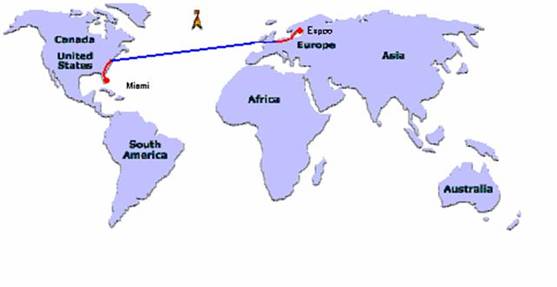
Fig7: World map:
On the ground : red
Submersible : blue
Earth distance between:
|
From |
To |
Distance [km] |
|
|
|
398 |
|
|
|
522 |
|
|
|
622 |
|
|
|
5856 |
|
|
|
1760 |
Total Distance: 9158 km.
This would be in an ideal case, so in order to minimize errors in calculations and take into account the irregularity of the ground and the unevenness of underwater terrain. So we take as the total distance.
9500 km. (+3 %)
Type of cable according to the topology:
|
From |
To |
Topology: |
Type of cable: |
|
Leppäväärä |
|
Aerial |
FXOHBMUK |
|
|
|
Submersible |
FXOHBMPPMW |
|
|
Underground |
FXOVDMU | |
|
|
|
Underground |
FXOVDMU |
|
|
|
Submersible |
FXOHBMPPMW |
|
|
|
Underground |
FXOVDMU |
In order to estimate the number of splices needed we assume that we take one splice for every 4 kilometers:
9500 / 4 = 2375
So we need 2375 splices.
References:
Books:
Web sites:
https://www.corning.com: general knowledge.
https://www.thorlabs.com: general
https://www.efunda.com: for the application examples.
https://www.carroll-ramsey.com/detect.htm: to find more information about PIN diodes.
https://www.mtmi.vu.lt/pfk/funkc_dariniai/diod/led.htm: anything about diodes
https://www.wcrl.ars.usda.gov/cec/java/capitals.htm: to find the earth distance between cities
Miscellaneous:
Physics lectures performed by Kari Vierinen.
Telecomunication Network & Cisco notes.+
Copyright © 2025 - Toate drepturile rezervate