|


 |  |
|
| |
 | Biologie | Chimie | Didactica | Fizica | Geografie | Informatica |
| Istorie | Literatura | Matematica | Psihologie |
INSTRUMENTAL ANALYSIS METHODS
The aim of analytical chemistry is the development of analysis methods and their practical application in determination of the chemical composition of substances;
Analysis methods can be classified, as described in figure 1, in qualitative and quantitative methods.

Figure1 Analysis methods sketch
A closer look at the particular methods employed enables a more thorough discrimination between certain types of analyses, as seen in figure 2.

Figure 2 Overlook of analysis methods
Instrumental analysis differs from chemical analysis by that the analytical signal is a physical parameter such as pH e, i, A, T %, L. This is further worked up using either a calibration function or a statistical method.
As calibration function can function any relationship between the analytical signal and analyte concentration
y = f (c, q1, q2, q3, , qn, d1, d2, dm (1)
where c = analyte concentration,
qi = sample characteristic parameters,
dj = apparatus characteristic parameters.
Depending on the procedure used for working up the analytical signal, the instrumental analysis methods are direct and indirect.
Direct methods are those methods for which the analytic signal value is used in directly calculating the concentration by means of the calibration function. There are absolute and relative direct methods.
Absolute methods require that the mathematical expression of the calibration function is entirely known (numerical values of all parameters known). Relative methods are not so demanding: the calibration function is not completely defined, and the analyte concentration is determined by comparison to one or more standard samples.
A standard sample is a sample containing an exactly known analyte concentration. Apart from standard samples we need reference samples. A reference sample contains no analyte, but all the others components of the samples.
The analysis stages require preparing standard and reference samples, measuring the analytical signal of each standard sample and defining the calibration function graphically or numerically (using interpolation functions).
y = a0 a1c a2c2 a3c3 . (2)
Some of the experimental procedures used are called calibration curve method, least squares method, comparison method, unique and multiple addition method.
Indirect methods require measurement of analytic signal variation. This, in turn, allows equivalence volume determination for titrations; analyte amount is calculated without using the absolute values of the signal.
The titration curve obtained in indirect methods shows the variation of the analytical signal as a function of the added titrant
![]() (3)
(3)
where m = amount of analyte in the sample,
Ve = equivalence volume in ml,
n = titrant normality,
f = titrant volumetric factor,
E = analyte equivalent.
The use of instruments imparts sensitivity, selectivity, accuracy and speed to these methods.
Regardless the measured parameter, any instrument used in instrumental analysis corresponds to a scheme very similar to that shown in figure 3.

Figure 3 Instrument block scheme
The parameter of interest is measured, the signal reaches the signal converter through a transducer unit. Here, it is transformed into an electrical signal and compared to a reference, so that, in the end, a number is produced.
The transducer is characterized by a transfer function, which is namely the ratio between the value of the entrance signal and the exit signal. Generally, the apparatus precision and sensitivity are better if the transfer function is linear, with a large slope.
Even in the absence of the analyte the instrument measures some signal, whose value is constant during the measurement, and is called background signal or noise.
For best results in experimental measurements, the signal to noise ratio should be as large as possible. Most instruments are equipped with devices that apply statistical
optimization methods such as signal averaging, integration, derivation, to improve the signal to noise ratio.
Electrochemistry is the "science of application of electricity to chemistry" (Oxford English Dictionary). Back in 1829 electrochemistry was considered "one of the connecting branches between remote divisions of the Philosophy of Nature". D. Brynn Hibbert, in the introduction to one his textbooks, considers it "the science of the interaction of the phases containing electrons and the phases containing ions".
Electrochemistry is widely studied
as it allows qualitative and quantitative analysis of many species in
solutions. As regards industrial
aspects, here are the most important ones: corrosion, for which the annual
price paid is around 60 109 $, energy storage, sensors for medical
and industrial applications, water purification, metal extraction and
recycling, or synthesis of substances. 6
% of the electricity consumed in
Electrochemistry is all about the interface between electrons and ions. There is some basic knowledge in the field that everyone should have before attempting to use it for qualitative and quantitative investigation.
Electrodes
The phase that conducts ions is known as the electrolyte. When a lump of solid containing electrons (the electrode) is introduced into the solution, it causes problems for the system to reorganize itself as to achieve an equilibrium state.
Electrolytes are usually liquid solutions, fused salts, Na b aluminate (ionic conducting solid).
The electrode is the phase where current transportation is due to electrons. It is generally made of solid or liquid metals or semiconductors.
When an electrode is introduced into an electrolyte, the species in solution equilibrate with the electrons in the solid, such as Ag ion at a silver electrode
Ag e ![]() Ag (4)
Ag (4)
The voltage (E) established is related to the free energy of the process occurring by:
![]() (5)
(5)
where n = number of electrons transferred per mole.
Two electrodes and their electrolytes are brought together, as in figure 4, and form a cell, whose overvoltage can be related to the free energy of the overall reaction by relationship (5). Reduction occurs at the electrode that donates electrons, and oxidation at the electrode that accepts electrons. Anions can be reduced at an electrode, as cations can be oxidized. In terms of equilibrium the oxidizing rate of a species at an electrode is equal to the rate of reduction.
Figure 4 Oxidation and reduction at an electrode
Whereas the electron has no options but to react at the electrode, the species in solution have the freedom to move. If they are charged in solution, they can move in response to the electric field that is set whenever there is a voltage difference between the two electrodes. Any species can diffuse if there is a concentration difference between two points in the cell. Such a concentration difference arises when an electrochemical reaction happens at the electrode surface, that is when a current flows.
Faraday's first law relates the current (I) to the reaction rate, v:
![]() [mol s 1] (6)
[mol s 1] (6)
In the absence of any imposed voltage, the electrode will response to being plunged into an electrolyte by accumulation of electrons at the interface. On the solution side, cations are drawn to the metal by electrostatic interaction. They bring along their own solvation sheaths. Water molecules solvate the electrode, and are oriented (being dipoles). By gaining intimate contact with the electrode, many negative ions tend to lose their solvation shells.
The binding of species to the electrode surface is known as contact adsorption, specific adsorption or superequivalent adsorption. Neutral organic molecules may also bond to the surface. The overall picture of the electrified interface is shown in figure 5.
Figure 5 Electrified interface
The assembly of the adsorbed ions and the attracted positive ions is the so called Helmholtz double layer.
Direct observations of the double layer can't be made. Charge separation at the interface creates a potential, that can be measured when related to other interfaces.
The measurement of the variation of surface tension with applied voltage of a mercury electrode confined in a capillary allows determination of the double layer capacitance and the surface charge. The experimental device is presented in figure 6.

Figure 6 Lipman electrometer
The position of mercury meniscus is monitored through a telescope. When the applied potential is varied, the meniscus position changes. If the height of the mercury reservoir is adjusted, the meniscus position is restored. The change in height is directly related to the change in the interfacial tension, which is related to the charge at the interface, i. e. the number of ions in the Helmholtz layer. In aqueous solution Hg acquires a positive charge. As more negative potential is applied, the charge is neutralized and the surface tension rises. The surface tension reaches a maximum at some potential where the surface charge is zero, after which falls.
Theories of the double layer should predict the potential across the interface, the extent of adsorption and other electrical parameters (capacitance). Historically, theories of the double layer started with a model in which a fixed layer of charges sat at the outer Helmholtz plan and displayed a linear potential drop from the electrode to the outer Helmholtz layer. This known as Helmholtz Perrin theory. Unfortunately, it holds only for concentrated electrolyte solutions. Then Gouy and Chapman assumed that the double layer is diffuse, spreading out into electrolyte bulk. This approach allows an infinite closeness of the species to the electrode. The theory is the antecedent of the Debye-Huckel theory of electrolytes, but it neglects the ion size. Stern sorted out the problem, assuming that the potential varies linearly with the distance up to the outer Helmholtz layer, and decreases exponentially afterwards.
The Galvani potential (or inner potential) at a point, f, is the work needed to bring a charge from infinity to the considered point. It may have the units of energy, but when divided by charge (in coulombs), the value is in volts.
Differences of Galvani potentials, Df, between electrode and solution are accessible, and represent the fundamental potential talked about in electrochemistry:
![]() (7)
(7)
Neither the Galvani potential, nor the Galvani potential differences can be measured, but the difference of two differences can be measured.
The Galvani potential difference is
regarded as the sum of two potential differences, the

Figure 7 Electrokinetic phenomena
A series of phenomena arise as a consequence of the double layer, when electrolyte or charged colloidal particles are allowed or caused to move. The relationship between these phenomena is shown in figure 7.
The essence of electrochemistry is that many species react at conductors, in solution, gaining or losing electrons. If this is allowed to happen, a current flows, an electron current in the wires connecting the electrodes, and an ion current in the electrolyte. All this chemistry is poised and about to happen even when no current flows; the fact manifests itself as a voltage that can be measured across the whole system.
An electrochemical cell is an assembly of two electrodes separated by at least one electrolyte solution.
If we mix solutions of iron (II) sulphate with cerium (IV) sulphate, the following reaction occurs
Fe2 Ce4
![]() Fe3
Ce3
Fe3
Ce3
The reaction can visualized in the sketch, with the electron leaping from iron to cerium ion.
The global reaction can be written as two separate equations:
Fe2 ![]() Fe3
e
Fe3
e
Ce4 e ![]() Ce3
Ce3
If the iron and cerium salts can be isolated, a wire must be used to pass the electron from Fe2 to Ce4 . This is shown in the next sketch. The dotted line indicates the separation of the two reactions.

If the two solutions were completely separated and the reaction went ahead, the bottle containing cerium would fill up with electrons, while the bottle containing iron would become positively charged. This is impossible, as, except on microscopic scale and for fleeting times, cells are electrical neutral. But our solution contains negative ions too, and although they take no part in the electrochemistry, as Ce4 is converted into Ce3 , it needs half a sulphate ion less, and as Fe2 is converted into Fe3 , it needs half a sulphate ion more, for electrical neutrality. This is accomplished by sulphate ions moving from cerium compartment to the iron compartment. In real life there would be also a tendency for positive ions to move as well, but let's suppose that the dotted line in our cell is an "ion-selective membrane", that only allows sulphate through. This is an electrochemical cell.
HALF CELL
In the cell above the two halves of the cell complete with electrode and electrolyte are known as half cells. This is not a trivial distinction, as it would be possible to take away the iron half cell and replace it with a copper wire in copper sulphate solution. Now copper dissolves, giving up two electrons
Cu ![]() Cu2
2 e (8)
Cu2
2 e (8)
and the overall reaction, after multiplying equation (8) by 2 is
Cu 2 Ce4
![]() Cu2
2 Ce3 (9)
Cu2
2 Ce3 (9)
Half cells can be treated independently (adding and subtracting them and their associated potentials), but real life measurements need two half cells.
In an electrochemical cell the electrode that supplies electrons into the half cell is the cathode, and the electrode that removes electrons from its half cell is the anode.
Thus, reduction occurs at the cathode, and oxidation occurs at the anode.
Electrode polarity may be either positive or negative, depending on whether the cell is generating a voltage through its own reaction or whether is being supplied with a voltage from an external source. Consider an anode at which oxidation occurs. The reaction happens, electrons will be coming out of the electrode, having been removed from whatever is being oxidized, and the electrode will be negative with respect to the cathode. If an external power source is being used to effect oxidation at an anode, it will be made positive with respect to the cathode, into which electrons will be poured.
Electrode Characteristics
If polarization means moving the voltage away from equilibrium, then the polarizable electrode allows voltage being shifted away from equilibrium value.
If electrode potential in the half cell Pt Ce3 , Ce4 , is moved away from the equilibrium in the positive direction, (by removing e ), Ce3 ion will give them up:
Ce3 ![]() Ce4
e
Ce4
e
A current flows and the potential
does not change much. If the potential
is moved away from equilibrium in the negative direction (compared to the
equilibrium value) Ce4 ion is reduced and
the current flows in the other direction. This system is
non polarizable, voltage being held near equilibrium by the flow of
current.
When Ce3 is taken away from the system, and the electrode is polarized in a positive direction, there is no easy oxidation to take place. Potential will shoot up, until is high enough to break down water. This half cell is a polarizable electrode.
Kinetically speaking, polarizable electrodes are involved in slow electrode reactions or are inert towards them, while the non polarizable electrodes are connected to rapid electrochemical processes.
These types of electrodes are of
use in different practical situations. In some cells we frequently require one electrode to have a constant,
known potential, that is to be a reference electrode. Obviously, the best reference electrodes
should be
non polarizable. But in the case of polarographic experiments,
the mercury drop should change its potential very fast. Then electrodes must be polarizable.
Practically, at a non polarizable electrode the system can't sustain higher and higher currents, and eventually the voltage will change. At a polarizable electrode there is a time when an electrochemical reaction will occur and current flows, slowing up the change in voltage. As regards Hg, there is a positive limit, as it oxidizes itself.
Reversible Electrodes
An electrode is considered reversible (Nernstian) if the reaction at the electrode comes rapidly to equilibrium. "Reversible" in electrochemistry is similar to "equilibrium" in thermodynamics. So the system can be moved smoothly through the equilibrium position. If the potential is made a little more cathodic, reduction occurs, and if it is a little more anodic, oxidation takes place. An ideal non polarizable electrode is reversible.
Sometimes electrodes (half cells) are said to be reversible to a particular ion. For example the hydrogen electrode is reversible to H , and HO ions; the calomel electrode is reversible to Cl .
If the electrochemical reaction does not occur, the electrode is non reversible.
Another cause of non reversibility is a chemical reaction that occurs at the electrode. The platinum electrode is non reversible to O2, as Pt oxides build up on the surface, giving a potential that arises from different electrochemical reactions (a mixed potential).
Electrode Potential
Consider an electrochemical cell where one voltage measurement is made between anode and cathode. How is this related to the Galvani potential differences throughout the cell?
The voltage measured by the voltmeter can be determined by starting from one side, walking along the circuit and counting all the potential differences, as they are encountered, until the other side is reached. At this point the sum will be the measured potential. Any boundary between phases (metal and solution, solution and solution or metal and metal) implies a change in potential.
Figure 8 Voltage across the electrochemical cell
Suppose the voltmeter has copper wires and the electrodes are made of platinum. The potential are thus
V = Df(Cu, Pt) Df(Pt, Ce4 /3 ) Df1,j Df(Fe2 /3 , Pt) Df(Pt, Cu) (10)
The potential, Df1,j is the liquid junction potential that arises from the presence of different solutions on either side of the cell separator. The direction in which an interface is crossed is important for the sign of the potential. Should be obvious that
Df(Cu, Pt) = Df(Pt, Cu)
Immediately equation (10) becomes
V = Df(Pt, Ce4 Df1,j Df(Fe2 , Pt) (11)
The interface between two different solutions can generate small but important potentials (up to 0.1 V). However, when necessary, the liquid junction potential can be minimized, in which case the measured voltage becomes simply the difference between half cells potentials, if both terms are written in the same direction (as the potential between the metal and the solution):
V = Df(Pt, Ce4 /3 ) Df(Pt, Fe2 /3 ) (12)
Both Df (Pt, Ce4 /3 ) and Df (Pt, Fe2 /3 ) are called electrode potentials.
Electrochemical Potential
The energy of a system can be expressed as a potential, in volts. Hence nuclear physicists mean by electron volt the energy required to move an electron through a potential of 1 V.
The chemical potential of a species is the partial derivative of the Gibbs energy with respect to the amount of the species. That is
 (13)
(13)
where nj refers to all the other species present. It is this quantity, m, that is minimized at equilibrium. The chemical potential is related to the activity of the species by
![]() (14)
(14)
Equation (14) takes no account of any electrochemical process. If a species is charged (zi) and at a potential f1, the electrochemical potential is defined as:
![]() (15)
(15)
At equilibrium in an electrochemical reaction the electrochemical potentials of the reactants and the products must be equal.
Always remember that electrochemical potential is an energy, the electrode potential is a voltage!
Measurements must always involve at least two electrode potentials. If the potential of just one half cell were known, all the others could be unraveled, by making cells with the known half cell plus the other one of interest and using equation (12). Electrochemists decided to consider a particular half cell which under defined conditions has a potential of zero. The half cell in question was the standard hydrogen electrode (SHE), a hydrogen electrode with a solution having pH = 0.0 (activity of hydronium ions 1) and the fugacity of hydrogen gas of 1. A typical practical form is depicted in figure 9.
 H (a = 1) H2 (p = 1 atm), Pt
Figure 9 Typical form of the hydrogen electrode
Although the SHE cannot be realized in practice, the potentials of other half cells relative to it can be determined. The standard electrode potential of a half cell, e0, is the potential of a cell made up with the half cell, with all the species in their standard states, and the SHE. The notion of standard state is for activities and fugacities to be unity, elements and compounds are to be in their most stable forms, and the temperature defined as 289.15 K (25 C). The scale of standard electrode potentials is written with the electrochemical reaction that occurs in the half cell written with the electrons on the left hand side. The reaction of the SHE is:
H e ![]() 1/2 H2 e0 = 0,0 V
1/2 H2 e0 = 0,0 V
e, the cell potential, is related to Gibbs energy by:
DG = n F e (16)
At constant pressure and temperature, reactions take place spontaneously if DG is negative (for full cells). Half cells may be compared by means of e0.
Consider the cell presented in figure 8. In the shorthand notation, the electrode is written first, followed by each electrochemically active species as one comes to them. A vertical bar represents a change of phase between species in equilibrium, e. g. an electrode and electrolyte. A double bar indicates that the potential arising from the phase change has been eliminated by a salt bridge. Commas divide species in the
electrolyte or electrode. It is important, the concentrations of the species may be included in parentheses after the species symbol.
Pt Ce4 , Ce3 Fe2 , Fe3 Pt
The voltage of such a cell is conventionally the potential of the right hand minus that of the left hand side:
ecell = eright half cell eleft half cell (17)
When writing an electrochemical cell these are the rules for making a full cell from two half cells, that will have the correct potential and will be the spontaneous reaction:
multiply through the reactions to give the same number of electrons in each;
write the reaction with the more positive electrode potential;
reverse the reaction with the more negative potential and write it underneath, reversing the sign of the half cell potential as well;
add the two reactions and the two electrode potentials.
A variety of electrodes (half cells) will be reviewed in the followings.
metal, metal ion electrode
One of the simplest types of electrodes is a lump of metal dipped into a solution containing one of its ions. This is known as "first kind electrode" and actually responds to the metal ion. Cu, Zn, Ag, Hg, Cd and Pb behave reversibly to their ions in aqueous solution. Even if they have the e0 value within the stability domain of water, Fe, W, Ni, Co, Cr are not used for electrodes, because of the oxide layers that make them quite irreversible. Difficulty comes with the alkali metals, because their e0 values are so negative (Na with e0 = 2,74 V, K with e0 = 2,925 V and respectively Li with e0 = 3,045 V) and react with water. The use of non aqueous electrolytes or molten salts represent a way out of the dilemma.
When we speak of a first kind electrode we use this type of a shorthand notation: Ag Ag
metal, insoluble metal salt, anion electrode
These electrodes comprise the most famous reference systems. If a Ag wire is oxidized in the presence of Cl , it forms a coating of insoluble AgCl. When immersed into Cl , a e is established with the half cell reaction
AgCl
e ![]() Ag Cl e = 0,2224 V (18)
Ag Cl e = 0,2224 V (18)
e does not depend on [Ag ]. The electrode is reversible with the concentration of the anion that forms a sparingly soluble salt with the metal. The metal activity is controlled by the anion concentration and the solubility product of the salt.
Please note that the silver silver chloride electrode (Cl AgCl) is not the silver electrode (Ag Ag ).
The calomel electrode is similar, with mercury (I) replacing silver, Cl Hg2Cl2 (e0 = 0,2681 V). In this electrode liquid mercury makes an intimate contact with solid mercury (I) chloride, which in turn is in contact with a potassium chloride solution of known molarity. When used as a reference electrode, a saturated KCl solution is used, although a 0.1 mol dm 3 solution gives a smaller temperature coefficient. The following table presents the potentials of most used calomel electrodes. These are "second kind electrodes", because the metal electrode responds not to the metal itself, but to an anion with which the metal forms a precipitate. The activity of the metal is therefore controlled by the concentration of the anion and by the solubility product of the salt.
e0 of a calomel electrode at different concentrations of KCl
|
[KCl] / mol dm 3 |
e / V |
|
0.1 |
0.335 0.00007(T 298) |
|
1 |
0.2810 0.00024(T 298) |
|
saturated |
0.2420 0.00076(T 298) |
third kind electrode
This type of electrode responds to the activity of ions of a different metal through the competition for anions with which each metal forms an insoluble salt.
Consider the mercury (II) EDTA
electrode: EDTA4 HgEDTA2 , Hg. HgEDTA2
is a very insoluble complex (![]() ) and so the concentration of the complex is nearly constant
and low. If calcium EDTA is added, the
concentration of EDTA4 becomes inversely
proportional to the activity of the calcium ions. The potential of the half cell,
ehalf cell
depends only on [EDTA] and the system works as Ca2
electrode.
) and so the concentration of the complex is nearly constant
and low. If calcium EDTA is added, the
concentration of EDTA4 becomes inversely
proportional to the activity of the calcium ions. The potential of the half cell,
ehalf cell
depends only on [EDTA] and the system works as Ca2
electrode.
metal gas ion electrode
The hydrogen electrode is an example of a gas electrode. The metal provides a source or sink for the electrons. It does not play any part in the equilibrium between H and H2. The equilibrium is set up between the gas and an ion formed from the gas.
Other examples are the oxygen electrode: H O2, Pt, with e0 = 1.229 V, and the chlorine electrode: Cl Cl2, Pt with e0 = 1.3595 V. Unlike the hydrogen electrode, that can be practically made and is a good reference electrode, the oxygen electrode is almost impossible to set up. Bubbling oxygen gas over platinum is acid of pH 0.0 does not give a potential anywhere near 1.23 V.
redox electrode
Any system with variable valence can, in principle, be the basis of a redox electrode. The potentials for most transition metal redox reactions are well known. When the metal ions are complexed, the potentials are not the same. The FeII / FeIII Pt electrode has a standard potential of e0 = 0.771. The hexacyanoferrate (II/III) couple shows in the redox reaction only a potential of 0.356 V:
[Fe(CN)6]3 e ![]() [Fe(CN)6]4
[Fe(CN)6]4
It seems reasonable to suppose that the potential of a half cell will change as the concentrations (activities) of the species involved in the electrochemical reaction change. Consider the cerium half cell and the reaction taking place
Ce3 ![]() Ce4
e
Ce4
e
A larger [Ce3 ] will shift the equilibrium to the left by increasing [e ], which means a more negative potential.
If we consider the general electrochemical half cell
o
Ox
n e ![]() r Red (19)
r Red (19)
Ox and Red will be charged to reflect the transfer of n electrons. o and r are the stoechiometric coefficients of the reaction. At equilibrium the electrochemical potentials of the reagents will equal those of the reaction products:
![]() (20)
(20)
Using equation (15) this gives:
 (21)
(21)
Each phase is at its own potential. The potential of the electron, fE, must always be that of the electrode, fM. If the reactants Ox and Red are in solution, they will have the potential of that phase, fS. Electrical neutrality asks that: o zO n = rzR. The Galvani potential difference is the difference between these two potentials, and equation (21) becomes
Df fM fS (22)
Df = (omO nme rmR ) / nF RT / nF ln(aOo/aRr ) (23)
The first term, containing the standard chemical potentials is the standard Galvani potential, Df0. Therefore,
Df = Df0 + RT / nF ln(aOo/aRr ) (24)
Equation (24) is Nernst relationship deduced for a single half cell.
Galvani potentials are immeasurable, so Nernst should be applied to electrochemical cells instead of a single half cell.
Take the iron cerium cell, Pt Ce3 , Ce4 Fe3 , Fe2 . The voltage of the cell is the difference between each metal solution Galvani potentials:
e = Df(Pt, Ce4 /3 ) Df(Pt, Fe2 /3 ) (25)
Then
 (26)
(26)
The standard electrode potential is
the difference between the standard Galvani potentials of the half cells,
![]() , and the sum and the difference of logs and the log of the
produce division of arguments. In other
words:
, and the sum and the difference of logs and the log of the
produce division of arguments. In other
words:
 (27)
(27)
This is Nernst relationship for a cell that exchanges one electron. When n electrons are being exchange, the relationship changes according to:
 (28)
(28)
If gases are involved, activities are replaced with partial pressures.
Not too many years ago the application of a potential and the measurement of a current when the system has come to some sort of equilibrium was all that electrochemical measurements were about. The appearance of Poggendorf bridge and, more recently, the cheap electronic devices and microcomputer has caused a revolution in the practice of electrochemistry. Not only can voltages and currents be measured quickly and accurately, but also every conceivable form of changing voltage can be applied to an electrode.
The electrode itself may be the object of study or it may be used only as a physical support for the electrons. The size of the electrode is determined by the nature of the experiment. As the electrodes become smaller, there is a greater strain put on the accurate measurement of the current passed. It is possible to fabricate electrodes that are so small (microelectrodes) that many of the problems associated with transport and resistance are negated.
Particular compositions
metallic electrodes are made of any type of conducting material. Foil, mesh or wire can be used, but it is preferable to present the electrode to the solution in a compact way. A long thin wire electrode would not be suitable because of possible variation along its length.
glassy carbon is widely used as electrode material, when a
chemically inert electrode is needed that does not have the catalytic power of
platinum. Because graphite has clouds of
p
electrons, it adsorbs a variety of molecules. The
glassy carbon
electrode is employed in studies of organic electroactive species and
analytical chemistry, asking for large analyte concentrations.
powder materials for electrodes can be
*compressed in a pellet:
A contact is needed between the pellet and the metal wire, by means of some kind of epoxy glue. The pellet is sheathed by immersion in molten hydrocarbon or silicone wax, to stop the contacting metal and glue being attacked by the electrolyte. The front face of the pellet needs polishing before the experiment to give a clean surface of the powder.
*deposition onto metal foils or meshes:
For metal oxides that are formed by the decomposition of a salt, the metal is dipped into a solution of the salt, dried in air, and heated in an oven to effect the decomposition. The process is repeated several times to build up a suitable layer. Meshes are good for this process, as they trap solution easily. Organic polymers that are formed by electrolysis naturally grow on the electrode. Direct deposition is a cheap and easy of making electrodes out of a powder, but often the underlying metal will be exposed to the electrolyte, and might interfere in the electrode process. Deposits are usually delicate and prone to disintegration.
*teflon sealing
The powder is mixed with a dispersion of polytetrafluoroethylene (PTFE) in water to form a slurry, that can be painted on to the mesh. Heating causes the PTFE to melt, and holds the powder firmly on to the mesh. Proportions must be just right. Too much PTFE and the powder particles are insulated from each other and the mesh; too little and the electrode will not hold together. Teflon is very hydrophobic, which is useful in some experiments with gases, but may stop electrolyte contacting the catalyst, thus lowering the surface active area.
*Hg electrode
Mercury makes a unique electrode because of its liquid nature. When inventing polarography, Heyrovsky was the first to describe the dropping mercury electrode (DME). Mercury is allowed to fall by gravity through a fine capillary tube. A drop of about 1 mm diameter grows then falls off, to be replaced by another, and so on. The mercury pool that collects at the bottom of the cell, conveniently acts as counterelectrode. This arrangement has the advantage that with each drop a completely new electrode is created in such a manner, that the diffusion to the surface is known. Metallic impurities that may plate on the surface dissolve into the drop as an amalgam.
Sometimes a single drop is held on the end of the capillary, and this is known as hanging drop mercury electrode (HDME). If the mercury is smeared over a carbon flat electrode or deposited on an electrode, the result is a mercury film electrode (MFE). This may be done by electrolysis of a solution of a mercury salt at the carbon electrode.
Some electrodes are designed to ensure a known and controllable flow of electrolyte over them. Other ways of presenting a material as an electrode to a solution are constrained by the physical form of that material (powder) or the type of experiment to be performed. Some common designs are shortly presented in the followings.
a porous electrode is very convenient for experiments in gases. The gas is introduced by the back of the electrode and not bubbled over its surface. Figure 10 shows a schematic view of a porous electrode. In the biporous electrode, the size of the pores is adjusted to be wider at the solution side and narrower at the gas side, which creates a better interface within the electrode.

Figure 10 Section through a porous electrode
Teflon bonded electrodes do the same job in a better way. By having hydrophobic channels gas can permeate the electrode, creating myriards of three phase interfaces.
a microelectrode is considered any electrode that has at least one dimension of the order of microns. A typical form is a disc (0,5 50 mm diameter), formed from the end of a metal wire or carbon fibber, potted in Teflon or epoxy resin. Lines, cylinders, hemi spheres, ring and array of rings are also being used. Currents measured with such electrodes range from pA to nA. This requires a suitable amplification of the current, and for the cell to be housed in a Faraday cage, to prevent stray fields causing interfering currents.
The advantages of microelectrodes are:
* they can be used in vivo;
* the stationary regime is rapidly reached;
*they have a negligible resistance and can be used especially when supporting electrolytes can't be introduced and for dynamic studies;
* allow a rapid change of the potential applied to the electrode. It means that they can be employed for monitoring rapid reactions, and electrochemical generation of short lived species.
reference electrodes (half cells), as mentioned before, are ideally polarisable.
The calomel half cell is an example of metal, insoluble salt, ion half cell (Hg, Hg2Cl2 Cl ). The reaction cell is
Hg2Cl2 (s) 2 e ![]() 2 Hg(l)
2 Cl
2 Hg(l)
2 Cl
and Nernst equation gives the potential:
![]() (29)
(29)
The constant includes the standard electrode potential of the mercury half cell and the solubility product of calomel. If the activity of chloride ion, aCl , is kept constant, the potential of the half cell, e, does not vary.
HgO and KOH may replace Cl , when the electrode is to be used in alkaline solutions.
If the reaction of interest is pH dependent, the solution of KOH may be omitted, and the electrode used directly in solution.
Cells
For equilibrium measurements of one half cell against another, the form of the cell poses no great problems. It may be that half cells contain species that would react chemically (as Ag+ and Cl ), in which case they need to be separated. If the passage of species needs to be severely impeded, a glass fritte or porous pot may be sufficient. More sophisticated devices are membranes, that let through molecules of a certain size, charge or chemical nature.
Separation asks for an electrolytic connection between the two compartments, using a salt bridge. Salt bridges are inverted U tubes, filled with the required electrolyte and agar agar gel. They are filled hot, and, when they cool down, the gel sets, making the bridge easy to handle. Each arm of the U tube is then dipped into its half cell and the electrolytic connection is made. If ions diffuse at similar rates through the bridge, the junction potential can be neglected. KCl is the salt of choice, but if chloride is precluded, KNO3 or NH4NO3 are accepted.
Three electrode cells are needed when performing dynamic studies. This design allows a fine control of the overpotential at the working electrode. The cell contains:
a working electrode, where the electrochemical process takes place,
an auxiliary electrode, the one through which current passes,
a reference electrode.

Figure 11 Three electrode cell
WE: working electrode; AE: auxiliary electrode; RE: reference electrode
A typical cell is shown in figure 11. An overpotential at the working electrode may be measured or controlled this way. At equilibrium, the voltage between the working and the reference electrode is
eWE RE = DfWE DfRE (30)
When current flows, in addition to the equilibrium potential difference, the overpotential at the working electrode (hWE) and a component of the potential caused by the resistance of the electrolyte between the working and the reference electrodes (I RWE RE) is measured. Even though no current flows between the working and the reference electrodes, the reference electrode does probe the voltage drop between working and auxiliary electrodes. Therefore,
eWE RE = DfWE, e + hWE DfRE, e + I RWE RE (31)
The difference between two measurements is
eWE RE eWE RE, e = hWE + I RWE RE (32)
If the "IR drop" can be made small or accounted for, the measured difference gives the overpotential. The IR drop is minimized by placing the reference electrode as near as possible to the working electrode. This is facilitated by a Luggin capillary. If the tip is near to the working electrode, the actual reference electrode can be in a separate compartment (see figure 11).
They are carried out at equilibrium, measuring potentials or the conductance of solutions; the current is under strict control.
Potentiometric sensors are the most important aspect of these methods. They determine the analyte concentration in a given mixture, and their response can be easily transferred into binary systems. Most sensors do not have moving parts, are small, and relatively cheap.
All determinations are based on the difference between the analyzed system and a reference system. The measured voltage of the cell is related to the activity of the ions of interest by the Nernst equation:
![]() (33)
(33)
When the ionic strength is low, activities may be replaced by concentrations without loss of accuracy. However, it means that more concentrated solutions need to be buffered to the same ionic strength as the reference solution, usually by the addition of a non interfering electrolyte.
There are two
basic types of potentiometric sensor. The most widely used is the
ion selective
electrode (ISE), in which a membrane separates the analyte solution from an
internal reference solution. An ion exchange
equilibrium is established at the membrane, and a potential develops. There are many examples of ISEs, such as the pH glass electrode and the fluoride
electrode.
The second class of potentiometric sensors are based on traditional redox reactions. These are useful for specific applications, but are prone to interferences, as any redox couple in the solution will compete for electrons from the electrode.
The strength of
these methods, that follow the Nernst equation is that a very wide range of
concentrations are covered by the measurable range of voltages. For an
one electron
process at 25 C,
a change of 0.06 V induces activity changes of at least 106. The drawback is that small errors in the
measurement of voltage lead to large errors in the calculated analyte concentration. 1 mV leads to a 4 % change in concentration.
Interferences
In an ideal world there would be an electrode for each analyte that would respond only to that analyte and nothing else. Real world is very different! If a voltage is generated at an electrode by more than one analyte, each of which follows the Nernst equation, the total potential measured is
![]() (34)
(34)
where ai = analyte activity
aj = activity of any interfering species j bearing the charge z
kij = selectivity coefficient
Values of kij are specific to each electrode and analyte solution, and equation (34) holds only for narrow concentration ranges. Values of k less than 1 mean that the
interfering species has a smaller effect on the voltage than the analyte, and greater than 1 show the species has a larger effect.
Figure 12 shows the effect on the plot of ecell against ai of interfering ion at different concentration and with different kij values. It becomes clear that a reasonable amount of interfering can render an ISE almost useless. Halides and cyanide mutually interfere; silver, copper and mercury interfere with the determination of other metals and, in general, similar ions (size, charge) interfere. Interferences can arise because of complex formation, that removes the free ion, or by secondary reaction at the electrode (CN displaces Cl from AgCl).

Figure 12 Potential variation in a cell containing an interfering ion of activity aX
I.3.1 Potentiometric determination of pH
pH is easily defined as
pH = log (aH) (35)
Nice and simple as the definition is, because of the impossibility of measuring single ion activities, it is useless as it stands. Still, there are pH meters, electrochemical devices that determine a solution pH relative to another solution of known pH. The problem arises in making a cell, for which the measured voltage reflects only the change in hydrogen ion activity. Cells may have liquid junctions, and the activities of different species will vary with ionic strength. Analytical chemists have agreed upon an operational definition of pH, derived from the electrochemical method of measurement:
 (36)
(36)
where e = potential of an electrode sensitive to [H3O ],
ebuffer = potential of an electrode dipped into a buffer solution of known pH.
The National
Bureau of Standards of USA defines the pHs
of buffers from measurements of the potential of a cell containing a hydrogen
electrode and a
silver silver
chloride reference electrode: Pt, H2 buffer, Cl AgCl,
Ag. This has no liquid junction
potential to take care of. NBS has
established 7 pH primary standards.
The quinhidrone electrode is a good example of a redox electrode used for pH measurements. It is namely a Pt electrode, dipped into a solution containing equimoleculare amounts of quinone and hydroquinone, and the redox equilibrium is

Both quinone and hydroquinone are sparingly soluble in water, which causes the activities of the species to remain constant. Against a reference electrode the potential of this half cell is
![]() (37)
(37)
The antimony antimony oxide electrode, Sb, Sb2O3 is also pH sensitive. The reaction is:
Sb2O3
6 H
6
e ![]() 2Sb3
3 H2O
2Sb3
3 H2O
Any species present in the system causes interferences.
The glass electrode is a half cell separated from a reference half cell by a glass membrane (see figure13). At each side of the membrane an ion exchange occurs between the ions present in the glass membrane (Na , K , Ca2 , Li , Ba2 ) and H3O ions in solution. Most of the action occurs within 100 nm inside, where the glass membrane is a hydrated gel. Inside the glass is dry and very little affected by solution.
The internal solution is 0.1 mol dm 3 HCl and contact is made through a silver silver chloride electrode that is reversible to chloride ion. The reference electrode is often a calomel electrode. The cell used is
Ag, AgCl HCl (0,1 M) glass test solution KCl (saturated) Hg2Cl2, Hg

Figure 13 Glass electrode
The potential, e, varies with pH according to equation (37). econst includes constants related to the ion exchange processes. At pH > 10 the membrane becomes sensitive to univalent ions, which leads to a negative error in the measurement of pH. There is another negative error when using the glass electrode in highly acidic solutions, pH < 1.
Redox couples present in solution do not affect the measurements, because there is no electron exchange involved. The electrode needs frequent calibration and should be used connected to an apparatus of large impedance.
Ion Selective Electrodes (ISE)
An ISE is a membrane electrode sensitive to the activity of one or more ionic species. The term "membrane" includes any separator between two solutions, one containing the analyte and other one a reference solution. There are several classes of ISE and they will be shortly presented.
A homogeneous membrane electrode is made from one single crystal or pastille of an insoluble salt (AgCl). The membrane is fixed at the end of a tube filled with an internal reference solution (figure 14). Contact is established by means of an internal electrode, reversible to one of the ions present in the internal reference solution. The fluoride electrode has a membrane of LaF3, an internal solution containing 0.1 mol dm 3 NaF and 0.1 mol dm 3 NaCl, and an Ag, AgCl internal reference electrode. The membrane conducts the ion in question and the electrode is free from interferences. The cell is:
Ag, AgCl Cl (0.1 mol dm 3), F (0.1 mol dm 3) LaF3 tested solution Cl (saturated) Hg2Cl2, Hg

Figure 14 Membrane electrodes
The potential depends on the ratio between concentrations of fluoride in the test solution and internal reference solution:
 (38)
(38)
The fluoride electrode gives reliable results for a concentration range from 10 6 to saturated solutions. At pH < 3 formation of HF interferes with the determination, and the only other ion this electrode responds to is hydroxide.
heterogeneous membrane electrodes have the active element dispersed into a physical support made of silicon rubber and PVC.
The liquid ion exchanger
electrode in figure 14 presents a porous, hydrophobic membrane (cellulose
acetate) holding a liquid ion exchanging resin. The
ion exchanger
fixes the ion of interest and carries it through the membrane. There is an equilibrium between the analyte
concentration in the tested solution and the analyte concentration in the
internal reference solution. Modern
designs use a polyvinyl chloride (PVC) membrane in which the ion exchanger is
introduced in a suitable solvent. When
the solvent is allowed to evaporate, the membrane with the ion exchanger
may be used in ISE fabrication.
Anion exchangers are either alkylamonium salts with long hydrocarbonated
chains or salts of a stable complex such as [M(phen)3]2 efficient in
determining ClO4 , NO3 , BF4
ions. Cation exchangers are usually long chain alkyl
anions such as
bis(n decyl)phosphates,
which is an efficient exchanger for Ca2 .
Neutral carriers depend on the size and shape of their cavities to act as efficient carriers for various ions. Natural antibiotics (valynomicyn) and macrocyclic compounds (figure 15) are used for ISE specific for K , Ca2 and other alkali metal ions.

Figure 15 Natural and synthetic carriers
ion selective field effect transistor
When making voltage measurements, the signal is usually fed to the gate of a MOSFET (metal oxide field effect transistor), which is the first stage of amplification. The potential on this gate determines the current flowing through the device and thus amplification is achieved. If an ion selective membrane is applied on the entrance gate of the MOSFET, an ISFET is obtained. A crossection in an ISFET is shown in figure 16. Impurities in the gate generate a reference potential. The major drawback is that the sensitive components of the MOSFET are exposed to the environment. This leads to a short life time (100 300 h) and the need for in situ conditioning before use.
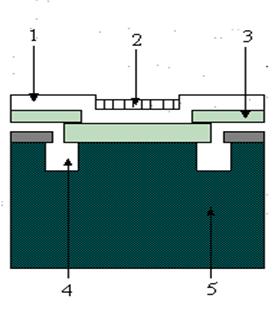
Figure 16 Cross section in an ISFET:
1 silicone nitride layer; 2 PVC membrane impregnated with ion selective compound; 3 silicone oxide; 4 n doped zone; 5 silicone substrate.
enzyme
substrate electrodes are sensitive to an organic substrate because the
ion selective
membrane is coated with an enzyme immobilized in a suitable matrix. The enzyme reacts with the analyte and the
concentration of the reaction product is detected by an ion selective
electrode.
Urea determination takes place this way: ureaze (the enzyme immobilized in the matrix) splits urea into NH4 and HCO3 and the glass electrode sensitive to ammonium determines the amount of NH4 produced in the reaction.
Potentiometrical sensors for immobilized enzymes
|
Sensor |
Detected species |
Analyte |
|
pH glass |
H |
penicillin, glucose, urea, acetylcholine |
|
NH4 glass |
NH4 |
urea, amino acids |
|
NH4 , gas |
NH4 |
asparagine, creatinine |
|
CO2, gas |
CO2 |
tyrosine, uric acid |
|
I ISE |
I |
glucose |
|
CN ISE |
CN |
amygdalin |
I.3.2 Potentiometric Titrations
An indicator electrode sensitive to pH may be used to monitor the pH during a titration. The plot of the voltage of a cell including a pH electrode and a reference electrode against titrant added has a shape similar to that shown in figure 17. The titration end point can be located graphically, and the equivalence volume is used to calculate the amount of species present in the system using
![]()
A pH titration curve may be use to calculate the acidity constant
values of weak acids and bases, considering the particular expression of
![]()

Figure 17 Titration curve for the titration of a base with an acid solution
Redox Titrations
The potential of a Pt electrode dipped into a solution containing the analyte is measured against a reference electrode. This is how redox titrations can be followed potentiometrically.
Precipitation Titrations
It is possible to titrate a solution containing chloride, bromide and iodide with silver nitrate to give the concentrations of each halide. A silver electrode is used with a reference electrode connected to the test solution via a salt bridge:
Hg, HgcCl2 KCl (saturated) NH4NO3 salt bridge halide solution Ag
As silver nitrate is added, silver iodide precipitates. The concentration of silver ions is low and determined by the solubility product of silver iodide. The potential increases slightly, as more silver is added, and more iodide is removed from solution. At the end point the potential increases to that determined by the solubility product of bromide. When all bromide is titrated, another potential step is seen as chloride reacts. Finally, when there is no halides remaining, the potential shoots up, as the concentration of silver ions is allowed to increase without hindrance as more silver nitrate is added. The titration curve is shown in figure 17.

Figure 17 Halides precipitation titration with AgNO3
Electrochemical methods of analysis are particularly useful in flow analysis. The basic layout of a flow injection experiment is shown in figure 18. A small volume (typically 100 ml) of the analyte is injected into a carrier stream flowing through an electrochemical cell. The electrode response appears as a peak, its height being proportional to the amount of injected analyte. Metal electrodes or coated metal wire electrodes are used. Sometimes several indicator electrode reference electrode pairs are coupled in series. If N cells, of which the potential varies as the Nernst equation, are connected in series, the total potential is a simple sum of N potentials and the slope of e versus ln (a) is NRT/F. Combining cell in series would reduce the error associated with such measurements and also improves the detection limit. However, the need for total insulation implies that the experiment must be done separately in N apparatuses. Any benefit gained would be lost in having to set up N titrations, N pH electrodes.

Figure 18 Diagram of a flow injection device
Copyright © 2024 - Toate drepturile rezervate